|
 |
TABLE OF CONTENTS
(title page)
FACTUAL INFORMATION
ANALYSIS
CONCLUSIONS
SAFETY ACTION
APPENDICES
|
|
|
| CASB Majority Report |
|
General | Breakup Sequence | Wreckage Examination | Impact Attitude Determination | Weapons and Military Equipment Recovered
Wreckage and Impact Information
General
The aircraft struck downsloping terrain near the top of a wooded hillside, 2,975 feet beyond the departure end of runway 22, a distance of 720 feet to the right of the extended runway centre line. Initial impact with the terrain was a tree strike at an elevation of 279 feet asl. Ground elevation at this point is approximately 240 feet asl.
From that point, the aircraft continued its descent into the trees; initial ground impact occurred 920 feet beyond the first tree contact.
The wreckage trail was about 1,300 feet long and 130 feet wide. The trail was on a track of 240 degrees magnetic (M). The mean downslope of the terrain over which the wreckage was spread was seven degrees.
Breakup Sequence
Two separate and distinct swaths were cut by the aircraft as it initially descended into the tree canopy. Upon investigation, it was apparent that the lower of the two swaths, to the left when viewed in the direction of flight, was cut by the horizontal stabilizer and that the higher swath, to the right side, was cut by the right wing. The tree-swath pattern was consistent with a nosehigh, right-wing-low attitude at impact.
As the aircraft descended lower into the trees, the different elevations of the two swaths evened out until there was no discernible difference at the point of ground impact.
Significant portions of the horizontal stabilizer and elevators had separated from the aircraft and were found between the initial tree strike and the point of ground impact. Portions of the right wing tip were also found between these two points. Damage patterns found on the leading edge of the wing tip, stabilizer, and elevator were consistent with a nose-up attitude and slight yaw to the right at impact.
At ground impact, the right wing sustained extensive damage. Both the number three and number four engines were tom from their pylons. A fuel-fed fire commenced at the impact point of the number four engine and spread down and across the wreckage trail in a diagonal manner toward the left side of the aircraft. The aircraft then began to yaw further to the right, and the empennage separated at the rear pressure bulkhead.
The remainder of the aircraft continued down the sloping terrain where it struck two rock outcrops, breaking off a substantial portion of the rear fuselage aft of the wings. By this point, the aircraft had yawed approximately 60 degrees to the right. The forward and centre sections of the fuselage then crossed a gravel access road where the left wing, remaining portions of the right wing, and cockpit section separated.
The centre section of the fuselage continued down the slope for a short distance where it came to rest in a shallow ravine. The lower portion of the wreckage trail was subjected to a severe fuel-fed fire which consumed a substantial portion of the wreckage.
A thorough search of the runway and the area between the runway end and initial impact point was conducted with the assistance of personnel from Canadian Forces Base Gander. No components or debris was located that could have come from the aircraft. There was no evidence that the aircraft tail had touched the runway during the take-off. (See Figure 1.6.)
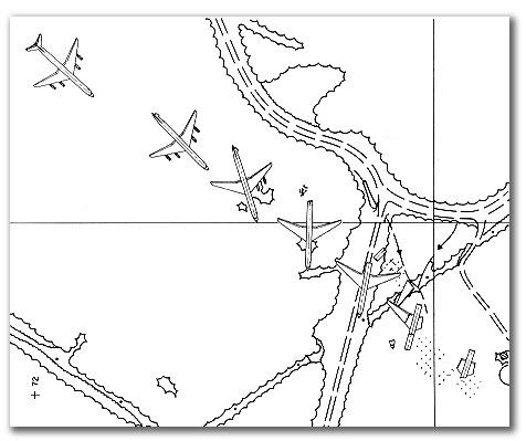
Figure 1.6. Aircraft Breakup Sequence
Wreckage Examination
An extensive examination of the wreckage was conducted over a period of several months. Initial examinations at the site were conducted to locate and identify as many of the remaining components as possible. Selected items were recovered from the wreckage and moved to a secure area for further examination. Certain items were then shipped to the CASB's Engineering Laboratory in Ottawa for detailed examination and analysis.
The initial examination of the accident site and wreckage was hampered by falling snow. Within five days of the accident, a thick layer of snow blanketed the site. As a result of the combined effort of the United States Army, the Royal Canadian Mounted Police (RCMP), and the CASB, a second examination of the site was conducted between 05 January and 07 February 1986. The site was systematically cleared of trees, tents were erected, snow melted, and detailed documentation and examination of the site completed.
All wreckage was recovered from the site and moved to a secure hangar at the Gander Airport, where it was arranged in a grid pattern which matched the grid pattern established at the site. A thorough examination of the wreckage was completed, and further selected components were forwardcd to the CASB's Engineering Laboratory in Ottawa.
Description of Damage
Structures
Most of the wing was destroyed by impact Significant portions were consumed by the intense post-crash fire. About 75 per cent of the aileron and flap surfaces were identified; however, less than 50 per cent of the spoiler surfaces were found. From the wreckage available for examination, no evidence was found of any pre-impact failure to the wing or any of its components.
The empennage had separated from the fuselage just forward of the rear pressure bulkhead. Portions had been subjected to the post-crash fire. The rudder was attached to the vertical fin and found at an angle of about 15 degrees left of neutral, with rudder trim at two degrees left of neutral. The upper parts of both components had been burned away. The root end of the right side of the horizontal stabilizer was still attached, and the jackscrew was still connected to the stabilizer. The amount of exposed thread corresponded to a 5.85-unit nose-up (ANU) stabilizer angle (this corresponds to a 6 ANU stabilizer angle on the flight-deck indicator +/-1 unit). The remainder of the right side of the stabilizer and all the left side had separated in several pieces after the first tree impact. The aircraft tail skid was recovered and examined. There was no evidence (i.e. scrape marks) that the empennage had struck the runway during take-off.
Reassembly of the separated portions of the stabilizer showed massive tree-impact damage. The elevators were damaged to a lesser extent due to the protection afforded by the stabilizer. Witness marks on the leading edge were consistent with an elevator position at impact of between 25 and 30 degrees trailing edge up. Impact damage at the hinges caused by overtravel was also consistent with an elevator-up position at impact.
Detailed examination of the elevator revealed the presence of a two-inch chordwise scratch on the leading edge of the left elevator. Corresponding to this mark was a mark on the plate covering the lightening holes in the left stabilizer rear spar. The nature of the marks was such that they could have been the result of a foreign object interfering with the movement of the elevator. It could not be determined if the marks were the result of impact or if they had existed prior to impact. There was no evidence of any pre-impact failure to the empennage or its components.
The fuselage had fractured into several sections and was substantially consumed by fire. From the wreckage available for examination, there was no evidence of any pre-impact failure associated with the fuselage.
Further examination of the wreckage was undertaken by a consultant employed by representatives of Arrow Air. This consultant found what he believed might be evidence of pre-impact explosive damage to the aircraft fuselage. The evidence consisted of a hole, roughly eliptical in shape, in a section of fuselage wall just aft of the right side forward door. The material that surrounded the hole exhibited an outward pucker, and the hole was assessed to be the result of an object striking the interior of the fuselage at high speed. A second hole was found in another unidentified section of fuselage. This hole was somewhat larger and also displayed outward deformation of the fuselage skin. As a result of his observations, the two sections of fuselage were subjected to additional examination at the Royal Canadian Mounted Police Central Forensic Laboratory and the CASB Engineering Laboratory. These examinations found no evidence to support the consultant's view that the holes had been caused by a pre-impact explosion. Forensic examination found no evidence of foreign material or explosive residue. The hole in the fuselage wall section aft of the right side forward door was attributed to an object being forced through the fuselage during breakup. In their examinations, CASB investigators observed other instances of curled over fractures (up to 360 degrees) which were directly attributable to impact damage which occurred during breakup. In the case of the second, larger hole, CASB investigators observed that the degree of curling at the edges of the hole was less than that of the other hole and that the edges were burned thin and were brittle, evidence of intense heat. The curled edges of this hole were attributed to sagging of the structure in the intense heat of the post-crash fire.
Systems Examination
The extensive impact and fire damage precluded a complete examination of the aircraft systems. As a result, the pre-impact integrity of the aircraft systems could only be determined as described below.
The systems examination was confined to an assessment of the position and pre-mpact serviceability of individual components. In certain cases, fire had destroyed identification data plates. This made it impossible to determine the original position on the aircraft of a part, where there was more than one of a specific type in any one system. Where necessary and possible, examination of system components included internal examination and functionaling.
Both aileron actuators were recovered; however, no other aileron system components other than linkages adjacent to the actuators were found. The position of the ailerons at impact could not be determined. No pre-impact faults were noted in the components examined.
No identifiable sections of the elevator control system between the flight deck and the rear pressure bulkhead were located during the wreckage examination. The control linkage in the aft section of the fuselage was broken and had tom loose. All damage appeared to have been impact related. No components of the rudder control system forward of the rear pressure bulkhead were found. The rudder hydraulic power package was in good condition with no external indication of pre-impact damage either to the package or to the attaching controls or linkages. The pack was removed, functionallyed, and no evidence of pre-impact faults was found.
The six flap actuators were recovered and examined to determine piston extension at impact. The cylinders were sectioned lengthwise, and the interior surfaces were examined. The severe postaccident corrosion of four of the cylinders precluded any determination as to the piston extension at impact. The two remaining cylinders were in good condition. Examination and analysis of the impact marks were not conclusive but suggested that flap position at impact was less than 25 degrees.
Eight of 10 flap tracks were recovered and examined for marks resulting from abnormal roller contact at the time of ground impact. Roller positions for various flap settings were measured on another DC-8-63 for comparison purposes. Multiple imprints were evident on most tracks. The most distinct marks were considered to be the most probable position at initial impact. Of the eight tracks recovered, only two could be identified as to installed position on the aircraft. These were the outboard flap, outboard tracks from each wing. Roller imprint marks on the right wing track were consistent with a flap position of 18 degrees. Several marks were observed on the left wing tracks consistent with a flap position between 5 and 12 degrees. Only one outboard flap centre track was recovered. It could not be determined on which wing it had been installed. Roller imprints on this track were consistent with a flap position of 17 degrees. Both outboard flap, inboard tracks were recovered, although installed position (i.e., left or right wing) could not be determined. Roller imprints on these tracks were consistent with a flap position of 23 degrees and 32 degrees respectively.
Both inboard flap, outboard tracks were recovered, although again, installed positions could not be determined. Imprint marks on one of these tracks were contradictory. Marks on the left-hand side of the track were consistent with a flap position of 50 degrees. Those on the right-hand side of the track were consistent with a flap position of 23 degrees. Imprints on the other inboard flap, outboard track were consistent with a nap position of 24 degrees. Only one inboard flap, inboard track was recovered. Again, it could not be determined on which wing it had been installed. Imprint marks on this track were consistent with a flap position of 18 degrees.
The three flap lockout cylinders were recovered and examined in an attempt to determine piston extension at impact. Each cylinder has an indicator rod to show the position of the piston. This rod is extended out of the cylinder when the flaps are up and is retracted when the flaps are extended. The three cylinders were severely fire damaged. The indicator rod of the outboard cylinder was fully retracted. All connections and the guide for the rod were burned away; the piston was partially melted. The mid-wing lockout was found with the piston at approximately mid-travel, and the piston was partially melted. The inboard indicator was in the fully retracted position. The piston was almost completely burned away; the end cap, including the indicator rod guide, was missing and appeared to have been destroyed by burning while still in place.
Since the outboard and mid-wing flap actuators are attached to a single flap panel which is sufficiently rugged to withstand significant twisting, it would not be possible for the outboard lockout cylinder to be fully retracted at the same time as the mid-wing cylinder was at half travel, unless a hydraulic line to the outboard actuator had ruptured. Similarly, for the inboard lockout cylinder to be in the fully retracted position, it would require rupture of a hydraulic line to an inboard actuator. The probability of two independent and simultaneous pre-impact hydraulic line ruptures is considered remote. Thus, it was apparent that some movement of the lockout cylinder pistons had probably occurred during aircraft breakup or the post-impact fire. Post-impact movement of the pistons was further supported by the extensive fire damage sustained by the lockout cylinders. Furthermore, the flap full-down position suggested by the inboard and outboard lockout cylinders was not supported by the roller imprint marks on the flap tracks. Thus, the condition of the three cylinders was such that no meaningful or reliable information with respect to flap position at impact could be determined.
The flap position indicator was recovered and examined. The pointer was relatively loose in the instrument and thus free to rotate, making the reading as found (38 degrees) unreliable. There was no impact damage within the instrument which would permit the determination of pointer position at impact.
Three of four wing slot actuators were recovered. One was fully extended, another was in the fully retracted position. The third, which was attached to a section of the left wing outboard slot, was found in the mid-travel position. However, upon examination, it was evident that this actuator had been in the extended position during the ground fire. The operation of the slot system is such that, when open, the outboard actuators extend, and the two inboard actuators retract The installed position on the aircraft of the other two recovered actuators could not be determined because of the absence of data plates. There was no evidence of pre-impact failure in the three actuators recovered.
Both lateral control spoiler actuators were recovered. Piston extension was consistent with spoilers extended on the left wing and retracted on the right wing. The control lever and linkage for the ground spoiler system were not recovered. The hydraulic actuator was recovered in the fully extended position, which is consistent with spoilers retracted. There was no evidence of pre-impact failure in either system.
The only major components recovered from the hydraulic system were two engine-driven pumps. They were severely damaged by the impact, but there was no evidence of pre-impact failure.
Thirteen of 16 fuel valves were recovered. Valve position at impact could not be determined.
The landing gear selector was not recovered. Examination of the landing gear hydraulic actuators and landing gear determined that the landing gear was extended at impact.
The shut-off valves for the wing leading edge and horizontal stabilizer de-icing system were recovered and examined. All were determined to be in the closed position. The type of valve installed is spring-loaded to the closed position, thus the valves close when electrical power is lost. Accordingly, no useful information regarding the operation of the ice protection system was gained.
The four fire extinguishing agent containers installed in the aircraft wings were recovered from the accident site. One container remained fully charged, while the other three had been discharged. Each container incorporates two discharge valves, and the plumbing and control system permits the agent in either container of one wing to be directed into either engine on that wing. Each discharge valve is operated by an electrically initiated explosive cartridge which fires a small projectile to rupture a diaphragm and release the agent. The agent in the containers can also be released as a result of thermal discharge. This occurs when the pressure within the container reaches a preset value and a pressure release disc is ruptured. This feature prevents the container from rupturing due to internal pressure increase as a result of the container being exposed to excessive temperatures. Examination of the three discharged containers showed one with two small raised areas on the exterior surface, each diametrically opposite to the discharge valves, indicating that the projectiles had been fired after the agent had been discharged thermally during the post-impact fire. A second container had no raised areas on the exterior surface. When the discharge valves for this container were disassembled, the discharge projectiles were found in place, indicating that this container had also discharged thermally during the post-impact fire.
The third container also had no raised areas on the exterior surface. Disassembly of the discharge valves for this container revealed that one explosive cartridge had been fired. The absence of any raised areas on the container surface opposite the position of the discharge valves indicated that firing of the explosive cartridge and release of the projectile had occurred while there was still agent in the container to dampen the force of the projectile and prevent denting of the container surface. Examination of the aircraft records determined that the third container had been installed in the right wing of the aircraft. The installation of the container was reviewed with reference to maintenance manual drawings and through examination of the containers installed in the right wing of another DC-8 aircraft. This review determined that the discharge valve with the fired cartridge corresponded to the number three engine.
The main instrument panel with instruments was recovered relatively intact, but severely damaged. The recovered items, which included light bulbs from various warning, caution, and annunciation light systems, were subject to detailed examination and analysis at the CASB's Engineering Laboratory.
Most instruments recovered were either too severely damaged for analysis or revealed no significant or reliable impact readings. Examination of the four engine pressure ratio (EPR) gauges revealed the following impact readings:
| Number 1 engine | - EPR 1.88 |
Number 2 engine | - EPR 1.34 |
Number 3 engine | - EPR 2.04 |
Number 4 engine | - EPR 1.96 |
The co-pilot's airspeed indicator sustained only minor damage. The airspeed indicator was equipped with an external circumferential ring with two moveable plastic "bugs" which are normally used to mark reference speeds during the take-off and approach phases of flight. Upon examination, these two external reference "bugs" were found at settings which corresponded to speeds of 144 knots and 185 knots. An internal reference "bug", located behind the glass face of the instrument and controlled by a rotary knob, was found at a seeing which corresponded to a speed of 158 knots.
The captain's airspeed indicator sustained significant burn damage. The internal bug was burned into position at 172 knots. No external "bug" ring was found on this instrument; it was determined that there was none installed at the time of the accident. The airspeed pointer indicated 165 knots.
A number of warning, caution, and annunciator lights were determined to be illuminated at impact. The time required for a light bulb of the type used to reach full incandescence is approximately 50 milliseconds. Thus, the breakup sequence of the aircraft must be considered in any assessment of the significance of the illumination of individual lights. Experience has shown that the illumination of lights is often the result of system failures caused by the gradual breakup of an aircraft. Thus, given the gradual breakup of the aircraft as it proceeded down the wooded slope, the illumination of any individual light is not considered reliable evidence of an aircraft system fault prior to impact.
The Master Fire Warning Light was recovered and examined. One of two bulbs in this light was determined to be off at impact. Examination of the other bulb was inconclusive.
One of four Engine Compartment Fire Warning Lights was recovered from the accident site and examined. It was determined to be off at impact.
Certain other lights considered to be relevant to the determination of the pre-impact integrity of aircraft systems were determined to be off at impact PTC (pitch trim compensator) - Extend/Fail; Hydraulic Reservoir Low Pressure; Rudder Control Manual; and Wing Slot Door.
Engines
All four engines were found within the confines of the wreckage area. They had broken loose from their mountings and had lost their cowlings during impact. The engines and their accessories were recovered from the accident site and shipped to the CASB's Engineering Laboratory in Ottawa for detailed examination and analysis.
The damage patterns observed in the numbers one, two, and three engines were consistent with ground impact at high rotation speed. The front compressor assemblies on all three had sustained catastrophic damage, and the compressor rear hub was twisted off in torsional overload. The front compressor turbine shafts were twisted in excess of 30 degrees. The rear compressor on engines one and three were destroyed. The number two engine rear compressor was relatively undamaged. However, it was noted that this section of the engine had not sustained any crushing of the structure surrounding the rear compressor. The accessory gearbox drive coupling on all three engines had failed due to torsional overload.
Damage patterns in the turbine sections varied between the three engines. However, it was evident that the variation in damage was the result of differences in the amount of damage sustained by the surrounding structure.
The bleed valves on engines one, two, and three were determined to be in the closed position at impact, which is consistent with engine operation at high power. Metallization (impingement on hot surfaces in the engine of semi-molten aluminum alloy and titanium from a damaged compressor) was present in the transition duct in all three engines.
The damage sustained by the number four engine was consistent with a lower rotation speed at impact than that of the other three engines. Only the first two stages of the front compressor were damaged as a result of rotation, and little rotational damage was noted on the front compressor/shaft/turbine combination. The bleed valve was determined to be in the open position at ground impact. Debris from trees was found on the valve duct wall on both sides of the valve. The rear compressor and its turbine, however, showed heavy rotational damage at the fifteenth and sixteenth stage compressors and first stage turbine, consistent with some engine rotation at impact. Metallization (aluminum alloy and titanium) was present in the transition duct.
None of the engines displayed any physical evidence of pre-impact distress. Each had ingested debris during impact with the trees and ground. The number four engine displayed the greaCOLSPAN=20 amount of wood ingestion. During engine disassembly, most of the wood debris was found in the high pressure section of the compressor.
The difference in impact rpm between the number four engine and the other three engines could not Be precisely determined. Several attempts were made to determine the impact rpm of the number four engine through measurement and analysis of the front compressor turbine shaft torsional twist. An initial attempt resulted in an estimated ground impact rpm well below the normal engine-out windmill rpm. This estimate was determined to be invalid because it assumed that torsional twist of the shaft occurs entirely within the proportional limit of the elastic region, whereas permanent twist can only occur if the shaft has plastically deformed and thus requires a plastic analysis. Further attempts by the engine manufacturer and CASB investigators, both of which assumed plastic deformation properties, resulted in contradictory findings. The manufacturer's analysis concluded that the ground impact rpm of the number four was only between 12.9 and 14.0 per cent lower than that of the other three engines. The analysis conducted by CASB investigators concluded that ground impact rpm was between 40 and 43 per cent of maximum rpm. Due to the contradictory nature of the conclusions of these analyses and the requirement to, in each case, make a number of assumptions, it was not possible to attach a high degree of reliability to either conclusion. However, the open engine bleed valve found on examination of the number four engine is consistent with engine rpm at or below 53 per cent N1.
The engine fuel control units (FCU) were recovered from the site and disassembled at the Air Canada maintenance facility in Montreal under the control and supervision of CASB investigators. No pre-impact failures were noted with the exception of a ruptured pressure regulator valve diaphragm in one FCU. The serial numbers of only two of the recovered FCU's matched those recorded in the aircraft records. The records indicated that these two FCU's had been installed on the number three engine and number four engine. The serial number of the FCU with the ruptured diaphragm did not match any of the serial numbers recorded in the aircraft records. However, its location in the wreckage suggested that it had been installed on the number four engine. All four units were free of contamination and, except for the ruptured diaphragm, were assessed as being in good condition.
It could not be determined if the diaphragm had ruptured prior to or as a result of impact. Except for the split in the diaphragm material, the diaphragm was in otherwise good condition, no deterioration in the fabric was noted. Ruptures of the type found are commonly found in fuel systems following a crash. They result from fuel pressure spikes which occur during aircraft breakup when fuel lines are pinched and collapsed.s conducted using an otherwise serviceable unit with the ruptured diaphragm installed indicated that the regulator was adjustable with the ruptured diaphragm. For a given throttle position, 6 per cent more fuel than normal would have been supplied to the engine with the ruptured diaphragm.
Three of the four fuel pumps were recovered and disassembled. No contamination or pre-impact failures were noted. Four fuel booster pumps were recovered and disassembled. No contamination or pre-impact failures were noted. A check of the serial numbers of these components determined that the serial numbers recorded in the aircraft technical logs did not match the serial numbers of the components installed on the aircraft. Installed positions could not be determined.
Three of the four engine constant speed drives were recovered and disassembled. No pre-impact failures were noted. They were assessed as being in good condition. Two of the recovered constant speed drives were determined to be from the numbers one and two engines. The installed position of the third recovered constant speed drive could not be determined. Only remnants of the fourth constant speed drive were recovered.
All eight engine inlet guide vane anti-icing valves were recovered. All valves were open, consistent with engine anti-ice being on at impact.
A separate examination of the engines was conducted by the same consultant employed by representatives of Arrow Air who had found what he believed to be was possible evidence of a pre-impact explosion in sections from the fuselage. This examination concentrated on inspection of the engine inlet guide vanes to see if evidence of engine ingestion of fuselage debris could be detected. His examination of what had been identified as the inlet guide vanes of the number three engine found three consecutive vanes which displayed a slight flattening on the leading edge. Examination of these vanes at moderate magnification showed that the middle one had a faint marking of red-orange color on the leading edge. The consultant hypothesized that the marks on the vanes were the result of ingestion of fuselage debris which had originated from what he considered to be a pre-impact explosion occurring just aft of the right side forward door. Later examination by CASB investigators determined that the inlet guide vanes in question were from the number one engine, and not the number three engine. It was further noted that the guide vanes had been subjected to intense heat during the post-crash fire and that any colouring material present prior to the fire would likely have burned off. Lastly, the red-orange colour observed on the guide vane was almost identical to that of the front-end loader which had been used to recover the engines from the accident site. Numerous examples of this post-accident red-orange paint transfer from the recovery machinery were evident on all four engines. CASB investigators concluded that the marks and colouring on the guide vanes occurred after impact, during wreckage recovery.
A consultant employed by a representative of one of the deceased flight crew members examined the engines and observed metal and fbre particles and what he considered to be unusual sooting in the area of the fuel nozzles of the number four engine. As a result, the number four engine fuel nozzles were removed from the engine and benched at the maintenance facility of a major Canadian airline. This testing was carried out by technicians of the airline experienced in the testing of fuel nozzles and in assessing their condition. No blocked nozzles were detected, and, in the opinion of the technicians, the flow patterns of all nozzles were acceptable. There were only a few nozzles where the fuel flow was not even throughout the full 360 degrees. Although they did not consider the condition of these nozzles to be suitable for installation in a newly overhauled engine, they were considered acceptable as in-service components. The technicians stated that any effect these nozzles could have had on engine operation would have been unmeasurable.
Further examination of the engine by CASB investigators found no evidence of heat distress indicative of poor nozzle flow patterns on any of the combustion chambers. The metal and fibre particles found on the nozzles were assessed to be the result of the tree/ground impact sequence. The particles covering the nozzle orifices were not solidly encrusted since they were easily pushed aside by the fuel flow - the nozzles were not mechanically cleaned prior to the. The fibre particles were identified as wood particles. The metal particles were assessed to be from the compressor section of the engine and the result of engine breakup during the impact sequence. The titanium and aluminum alloy metallization on the surface of the transition ducts of all four engines confirms that debris was being propelled through the engines during the breakup sequence.
The sooting in the area of the nozzles was considered consistent with the disruption of engine airflow and resulting changes to the fuel/air mixture that would have occurred due to tree ingestion.
At the request of the Board, additional examination of the number four engine was undertaken by an independent metallurgical engineer. The primary purpose of this examination was to assess the pre-impact condition of the engine and estimate its power output at impact. Upon completion of his examination and analysis, the consultant concluded that:
- The number four engine did not exhibit any component failure or malfunction prior to impact with the trees.
- The number four engine had not flamed out by the time of initial impact with trees.
- The number four engine was damaged due to ingestion of tree fragments and ground impact.
- The number four engine bleed valve opened due to engine deceleration that most likely occurred as a result of ingestion of tree fragments.
- The number four engine power setting at initial tree impact could not be established with certainty; however, the observed engine damage caused by tree fragment ingestion and resulting deceleration was consistent with high power setting.
Thrust Reversers
All four engine thrust reverser assemblies were recovered from the accident site and subjected to detailed examination and analysis.
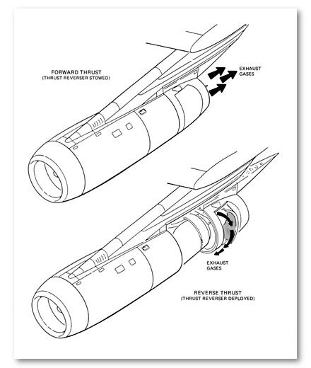
The deployment of the thrust reversers involves two actions: the rearward movement of the translating ring with the deflector doors in the faired position; and a final rearward movement of the translating ring (approximately seven inches) during which the stop on the latch rod contacts and operates an actuating mechanism, causing the deflector doors to open. The deflector doors can only be in the deployed position if the translating ring is in the full-aft position. (See Figure 1.7.)
The number one reverser was heavily damaged by impact but had remained relatively intact. The engine exhaust nozzle had separated from the engine at the aft engine flange and remained trapped inside the reverser assembly. The outboard deflector door was pulled slightly aft but was essentially faired with the translating ring. The inboard door was pulled partially out at the forward edge and the rear edge had buckled the adjacent area of the translating ring inward. Examination of the deflector door upper actuating arm showed marks in the slots adjacent to the arm, evidence that the doors were faired at impact. The skin and structure around the lower actuating arm was deformed inward, trapping the arm in the deflector door closed position. Further evidence that the translating ring had been in the forward position was provided by the position of the slider on the lower track; it was found close to the forward end of the track. It was concluded that the number one reverser assembly had been in the forward thrust position, with the deflector doors faired and the translating ring in the forward position (stowed) at impact.
The number two reverser assembly was substantially damaged and torn into a number of separate pieces at impact. The engine exhaust nozzle had torn from the engine just aft of the rear flange. The translating ring and the deflector doors were heavily damaged by impact. The aft mount of the reverser lower track remained attached to the nozzle together with the slide and a portion of the lower forward section of the reverser translating ring. The slide was towards the aft end of the track but was still more than 16 inches forward of the rear stop. Only the outboard door remained attached to the largest piece of the translating ring. When recovered, this door was in the faired position relative to the ring structure but was not trapped solidly in this position, and movement could have occurred during breakup. However, witness marks at the upper actuating arm of the outboard door indicated that it was in the faired position at the time of major crush. The inboard deflector door was torn into two main pieces. A heavy scrape mark in the material at the edge of the slot around the inboard door lower actuating arm gave clear indication that the door had been pulled from the faired position during ground impact. The outer cylinder of the hydraulic actuator was found near the forward end of the piston rod; the cylinder wall was ruptured longitudinally from an internal overpressure. Such damage could only occur if the piston rod, which is attached to the translating ring, was forward when ground contact caused it to be moved violently aft relative to the pylon. It was concluded that the number two reverser was not in the reverse thrust position at impact. The position of the slide on the lower track was attributed to scrubbing action during impact which occurred before the slider was trapped by track deformation.
The number three reverser had been completely flattened during impact, trapping the engine exhaust nozzle inside the translating ring, clear evidence that the reverser was in the stowed position at impact. The slide was near the forward end of the track. The inboard deflector door was torn in two. The lower portion was trapped in the faired position.
The outboard deflector door was also torn in two. Both the upper and lower sections were found in the faired position relative to the attached pieces of the translating ring. The hydraulic actuator had broken away from the reverser and the pylon. The gland nut and inner sleeve were at the forward end of the piston rod, and the cylinder was split longitudinally from internal overpressure. This overpressure damage was consistent with the translating ring being in the forward position at impact. It was concluded that this reverser assembly was in the forward thrust position with the deflector doors faired and the translating ring in the forward (stowed) position at impact.
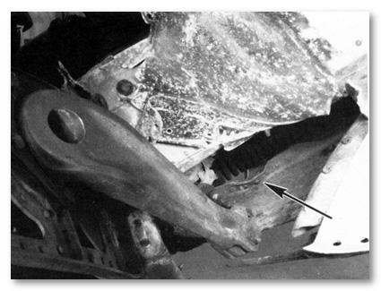
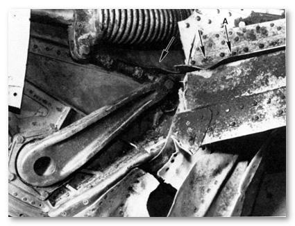
The number four reverser assembly had separated from the exhaust nozzle at impact. The forward loop of the translating ring assembly was broken with pieces missing from both sides. The lower deck was twisted 180 degrees around the rear section of the ring so that the forward face of the upper part of the translating ring was at one end of the assembly and the forward face of the lower portion was at the other end. The outboard deflector door was trapped by the structure in the faired position at the lower hinge point. The metal skin in this area was deformed inward, trapping the actuating arm in the faired position. The upper actuating arm for this door was torn away from the translating ring, but there were clear witness marks on the slot edge showing that the arm was in the faire I position at the time this damage occurred (Figure 1.8.). The inboard deflector door was torn away from the upper attachment point and was twisted to the deployed position. There was moderate to heavy damage to the forward edge of this door. There were deformed areas to the aft end of the actuating arm slots at both the upper and lower hinge points, evidence that the actuating arms for the inboard deflector door were also in the faired position at impact (Figure 1.9. and Figure 1.10.). The lower track was severely twisted but remained attached by the slide bracket to the forward edge of the translating ring. The slide was within 12.5 inches of the forward position and could not have slid forward after this impact deformation had occurred (Figure 1.11.). The hydraulic actuator was near the forward end of the piston rod. The outer cylinder had split lengthwise, with the material around the split bowed out (Figure 1.12.). This evidence was consistent with rapid extension of the actuator by external forces, and further confirmed that the translating ring had been in the forward position at the time of ground impact. It was concluded that the number four reverser was in the faired position with the translating ring in the forward (stowed) position at ground impact.
No failures were noted in any of the four reverser systems other than those resulting from impact.
|
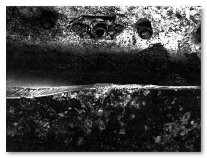
OUTBOARD DEFLECTOR DOOR UPPER ACTUATING ARM AREA OF NO. 4 REVERSER. ARM HAS BEEN PULLED OUT OF SLOT BY CRASH DAMAGE. NOTE DAMAGE IN AFT END OF SLOT AT ARROW.
|
|
THRUST REVERSER NO. 4 INBOARD DOOR LOWER ACTUATING ARM. SKIN HAS BEEN CUT AND FOLDED BACK TO SHOW DEFORMATION IN EDGES OF SLOT (ARROWS). NOTE THAT ARM IS IN THE DOOR DEPLOYED POSITION
|
|
VIEW OF DAMAGE TO EDGE OF SLOT AS SHOWN IN FIGURE 1.9. AT A. DAMAGE PATTERN SHOWS ARM MOVED FROM THE DOOR FAIRED TO THE DOOR DEPLOYED POSITION AFTER INITIAL IMPACT.
|
|
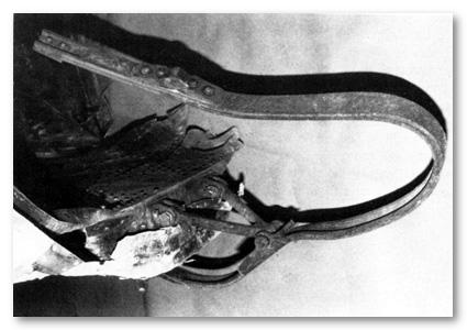
THRUST REVERSER NO. 4 LOWER TRACK. AFT END OF TRACK IS AT TOP IN PHOTOGRAPH.
|
Impact Attitude Determination
Using analytical plotters, three dimensional measurements were made of 378 trees which had been cut by the aircraft prior to ground impact (See Figure 1.13.). A 1/100 scale model of the treecut zone was then constructed, and a detailed 1/100 scale die cast model of a Douglas DC-8-63 aircraft was mated to the tree pattern (See Figure 1.14.). Flaps were placed on the model at an 18-degree configuration to match post-crash investigation findings. By accurately measuring the orientation of the aircraft model in the tree pattern at increments along its flight path, the attitude of the aircraft and the flight path angle were determined. Measurements indicated that the aircraft first contacted the tree canopy in a seven-degree right bank, nine-degree pitch (the angle between the longitudinal axis of the fuselage and the horizontal), and a 10-degree yaw right attitude, on a descending, 12-degree flight path angle (the angle between the flight path and the horizontal).
Weapons and Military Equipment Recovered
A variety of military weapons and weapon components was found scattered throughout the accident site. A list of recovered items which were identifiable follows.
| Weapon Type | Number Recovered |
| Pistols | 25 |
M16 (complete
or components) | 202 |
| M203 | 24 |
| M60 | 2 |
| Rifle | 1 |
There was no evidence found of any military ammunition or explosive device. Several practice-type devices and training aids were recovered. All were inert and contained no explosives.


|
|